How I Designed (and built) My Own Pen Plotter
For the last few months, after reading Preslav Rachev's book Generative Art in Go, I have been playing around with writing algorithms that create interesting graphics. I eventually ended up building a modular canvas library for Rust to make that easier to do, for me and other people.
After making a few algorithms and posting them to the web, I started looking around for more inspiration. I happened upon a video with this pen plotter:
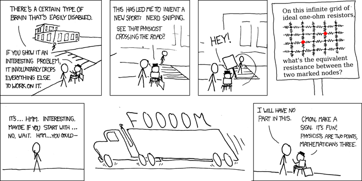
I was amazed. A robot that could draw vector graphics? I had been nerd sniped.
The Math
The mathematics involved interested my especially. How do you translate to rotations of motors? It intimidated me a little at first, but once I sat down and worked it out, I realized it was surprisingly simple.
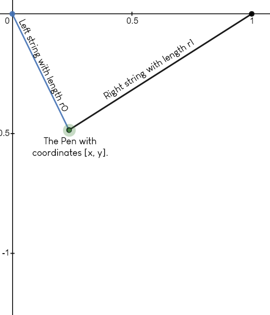
We consider that the two motors are simply lengthening or shortening each string a specific amount. Here are the equations that dictate the length of each string, given a point , and a distance between the two motors.
Is This Actually Going to Happen?
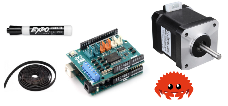
I initially sat down and did the math out of curiosity. I wasn't planning on building anything. After realizing the elegant simplicty of the math, I falt empowered to go through with it. I threw together a parts list.
Materials
- Whiteboard
- Expo Marker
- 2 Stepper Motors
- 3D Printer Timing Belt
- Arduino
- Adafruit Motor Shield
- 12V 2A Power Adapter
- Duct Tape (as any project requires)
I wanted to build this from scratch, without using anyone else's designs or software.
I order the materials off Amazon and soon enough, I had everything I needed.
Putting It All Together
The first step was to solder the motor shield onto the Arduino, and wiring up stepper motors. I used my school's laser cutter to make a little bracket.
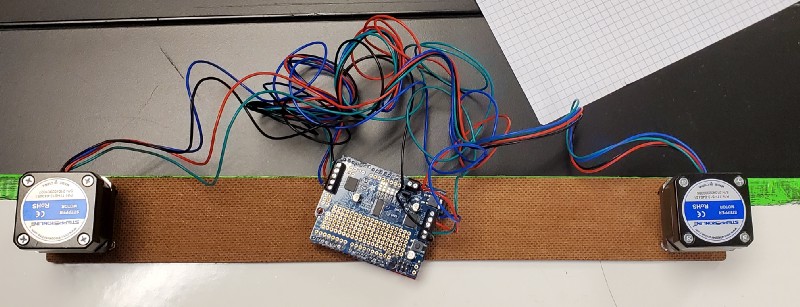
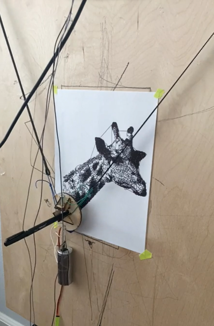
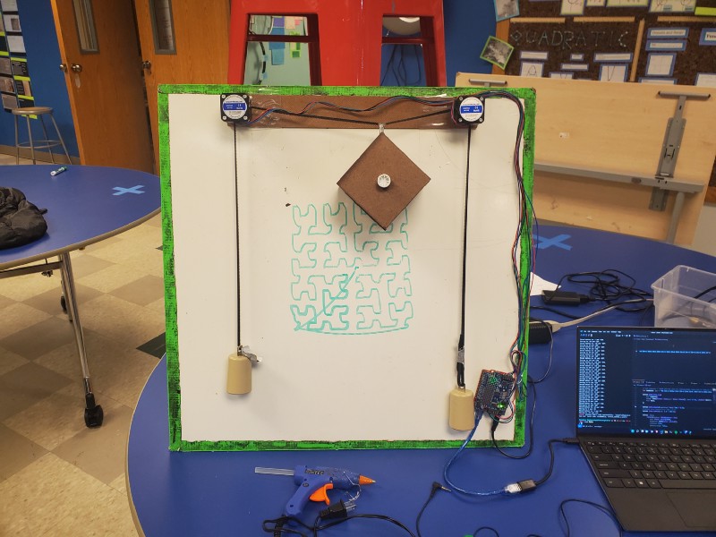
I am using weights to balance the belts on the motors. I mounted it to a whiteboard so I can iterate in software faster/easier.
I initially didn't have the timing belt, so I prototyped with an old length of wire. This is the last picture before I wrote all the software, which I want to talk about before I show you that version.
The Software
There are two, separate programs that, together, make the plotter work. The first is running on the Arduino, accepting commands over serial from the second, which is running on a USB-connected computer (my laptop).
There are three main reasons there needs to be a laptop in the system:
- The Arduino doesn't have enough program memory
- The Arduino cannot easily accept files (like SVGs)
- It takes forever for an Arduino program to compile and upload, which makes iteration frustrating.
Arduino
The Arduino is running a very simple loop:
- Receive two 32 bit signed integers over serial (one for each motor)
- Linear interpolate the stepper motors to positions described by received integers
That's it. It's important that the time it takes for each motor to reach it's destination is the same.
Laptop
The laptop is doing all the math.
I am used my canvas library Denim to do all the virtual drawing. I just added a renderer that:
- Converts all points to a sequence of belt-lengths
- Converts belt-lengths to sequence of motor movements
And sent the resulting motor movements over serial to the Arduino.
I also wrote a quick little parser using nom to parse and execute the math commands you can find inside SVG <path> elements.
Final Results
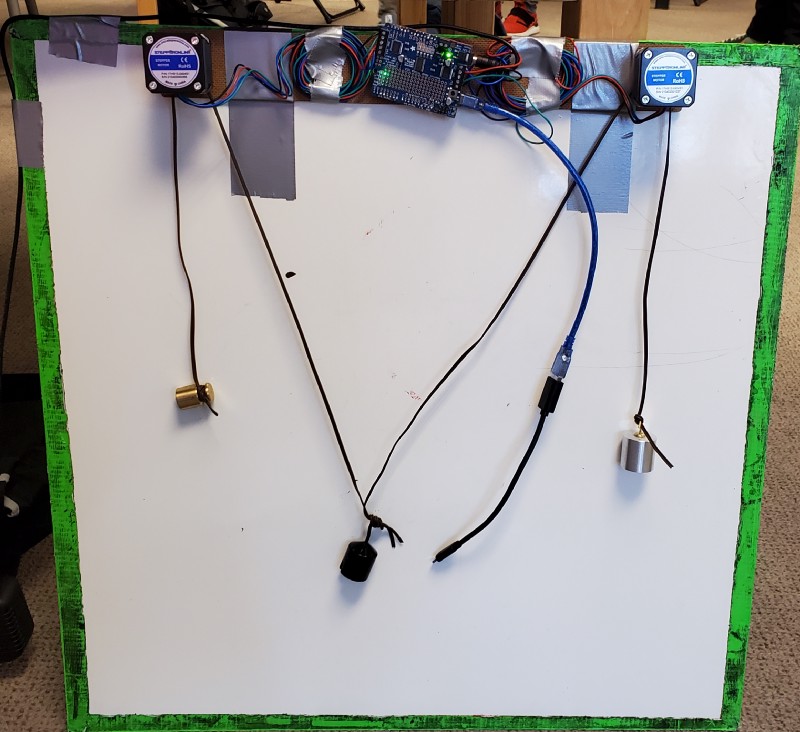
As you can see, I also made a big, rectangular box, to hold the marker. It worked alright, but not great. You also probably noticed the main limitation of my design: it cannot lift the marker off the whiteboard.
I figured the roughness was mainly due to unbalanced weights and the slant of the whiteboard. I adjusted everything and tried again.
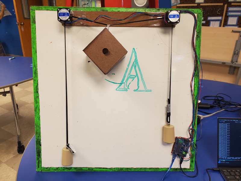
Take Two
This one is much better. The lines are crisp, and exactly where they are supposed to be. At this point I wanted to try something a little more advanced out. Something a little more generative.
The First Hilbert Curve
After seeing the plotter draw a Hilbert Curve, I felt proud and a little disappointed. The corners aren't crisp, the lines aren't straight. Frankly, it looks like it was drawn by a two-year old.
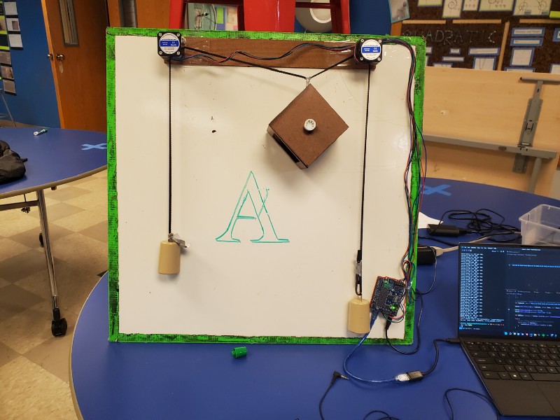
Solving the Issue
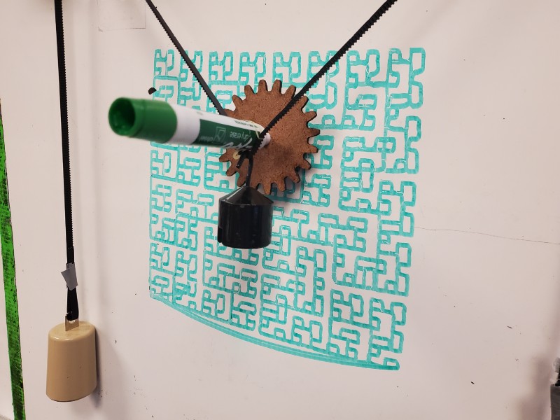
It worked! Now all the lines are precise, crisp, smooth. The biggest issue is that the marker itself rotates as it moves. That wouldn't normally be an issue, but the marker is chiseled, so it results in varying levels of pressure on the whiteboard.
Conclusion
This was a really cool project. I learned a lot. I am not very experienced with robotics, so this really challenged me. I intend on continuing working on it. I want to add the ability for the pen to lift off the canvas, and really solidify the marker holder. Most of all, I look forward to taking my projects into the real world.
Published October 18, 2022 at 6:00 AM
Proofread by Harper.
Comments
Other Stuff
Markov Chains Are the Original Language Models
Back in my day, we used math for autocomplete.
Hacker News sans AI
I like HackerNews, but I don't love that so much of it has turned into discussion of a single topic: AI. This is a version of HackerNews, filtered to remove any article focusing on __AI__. Refreshes about every ten minutes.
Why I Talk to Myself
It's not easy, but I think it's one of the best habits I've ever built.